Idatalink Alca Wiring Diagram
Set ignition to off position. Set ignition to off position.
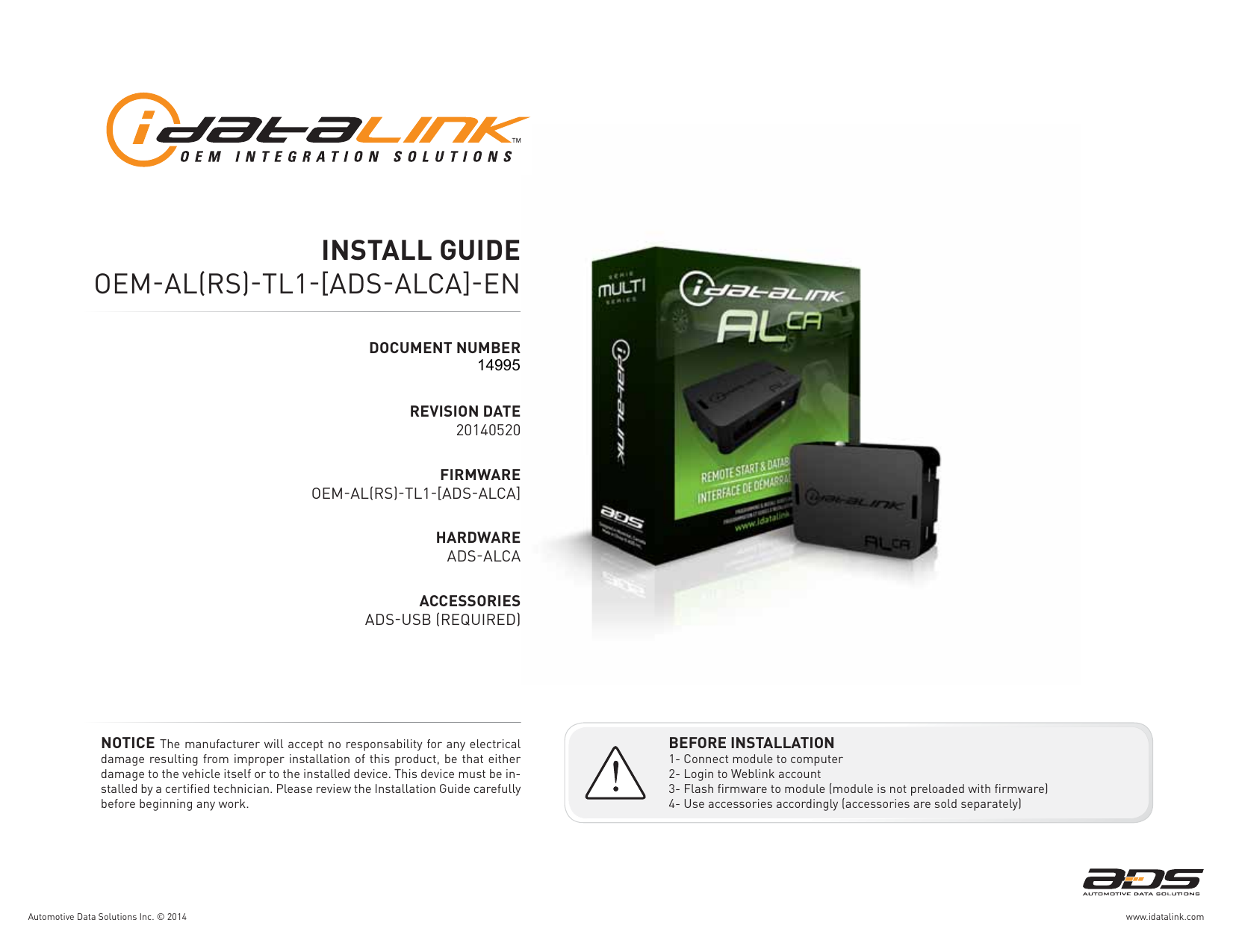
Idatalink Alca Wiring Diagram Wiring Diagram
The original member of the idata™ family.

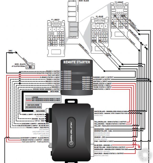
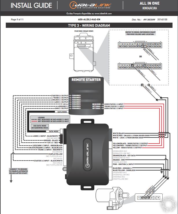
Idatalink alca wiring diagram. Set ignition to off position. Connect every wire shown in step 1 and step 2 of the wiring diagram. Data immobilizer bypass available where applicable.
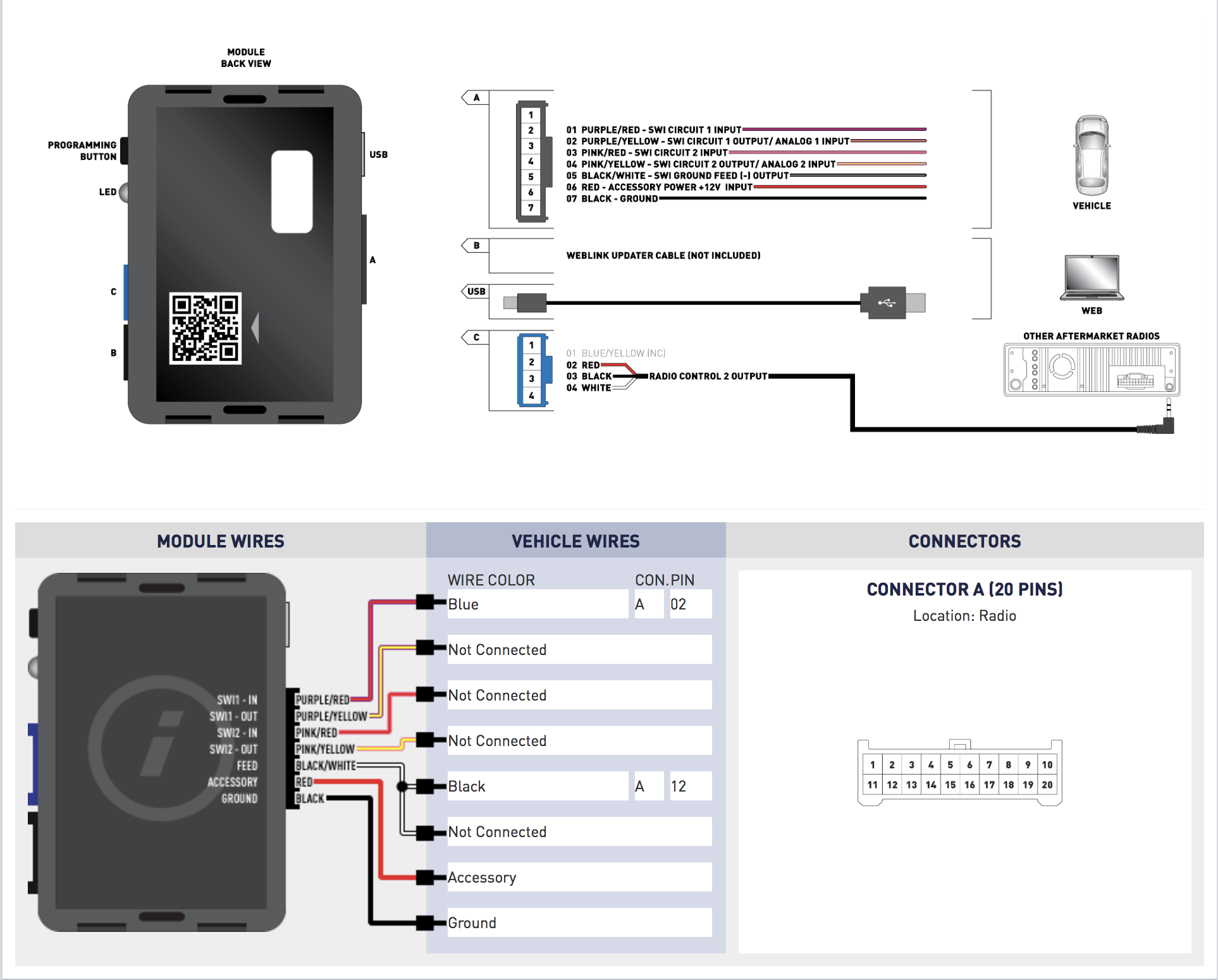
(see the vehicle wire chart reference for wire colors) step 6 • plug the aftermarket radio harnesses into the aftermarket radio. Wait, led 1 will ash green rapidly. Wait, led 1 will ash green rapidly.
Set ignition to on position. Connect every wire shown in step 1 and step 2 of the wiring diagram. 01 engine start stop off acc on start 02 03 [x] 04 05 [y] 06 07 [z] 08 [z] 09 10 11 [y] 12 13 14 >> it is mandatory to exit the module navigation
1 2 > share thread tools display modes sponsored links * registered users of the site do not see these ads. Wait, led 1 will turn solid red. Disconnect every wire shown in step 2 and connect every wire shown in step 3 of the wiring diagram.
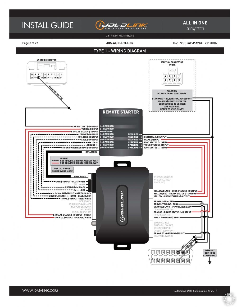
The viper trunk release will not work while the engine running / remote started. Set ignition to on position. Wait, led 1 will turn solid red.
In valet mode, the remote starter is not functional. Immobilizer bypass module doorlock & canbus interface. Set ignition to on position.
Set ignition to on position. Page 1 of 2 1 2 > « previous thread | next thread » thread tools show printable version email this page display modes linear mode switch to hybrid mode switch to threaded mode posting rules you may not post new threads Wiring diagram not merely gives comprehensive illustrations of everything you can perform, but in addition the methods you need to follow while doing so.
Set ignition to on position. Set ignition to on position. 0:00 intro0:26 what is transponder chip?0:54 unboxing1:21 checking wires2:46 flashing idatalink bypass module5:18 checking bypass module wires6:46 finding ca.
The hood status will only be available if you have the factory hood pin. See the compatible accessories page for details. Wait, led 1 will ash green rapidly.
Disconnect every wire shown in step 2 and connect every wire shown in step 3 of the wiring diagram. Wait, led 1 will turn solid red. Connect every wire shown in step 1 and step 2 of the wiring diagram.
Why i gave it 5 stars, the website gives you a schematic, including all the wires to use. Disconnect every wire shown in step 2 and connect every wire shown in step 3 of the wiring diagram. Check the brake connection as illustrated in the wiring diagram, if applicable, and call technical support.
As isit www.idatalink.com t dt dtais rev. The idatalink install chart does not show the necessary h3 ignition wire connections from the viper to the civic's ignition switch harness or the +12v power and ground connections.
Idatalink Alca Wiring Diagram Wiring Diagram

Mazda 2 Viper & ALCA quick look over needed
idatalink
Idatalink Wiring Diagram Wiring Diagram
Idatalink Wiring Diagram Wiring Diagram
Idatalink Wiring Diagram Wiring Library
Idatalink Wiring Diagram Wiring Diagram

������️ DIY Fix Install Remote Start RS2G3 + ADS ALCA
14 Viper Remote Start Wiring Diagram Free Wiring Diagram

Idatalink Wiring Diagram Wiring Diagram

Idatalink Alca Wiring Diagram Wiring Diagram
55 10 Pin Alarm Wiring Diagram Wiring Diagram Plan
Idatalink Alca Wiring Diagram Wiring Diagram
Idatalink Alca Wiring Diagram Wiring Diagram
viper install wiring diagram, Style Guru Fashion, Glitz

5806v Wiring Diagram Wiring Schema
2011 subaru impreza double bypass
Idatalink Alca Wiring Diagram Wiring Diagram
Idatalink Alca Wiring Diagram Wiring Diagram